- ALL COMPUTER, ELECTRONICS AND MECHANICAL COURSES AVAILABLE…. PROJECT GUIDANCE SINCE 2004. FOR FURTHER DETAILS CALL 9443117328
Projects > MECHANICAL/AUTOMOBILE > 2019 > FABRICATION > INDUSTRIAL
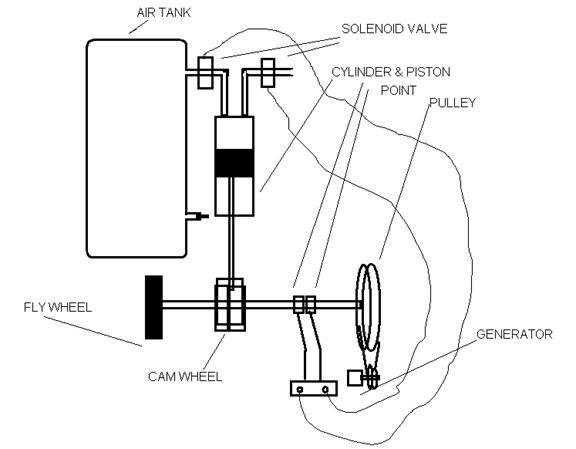
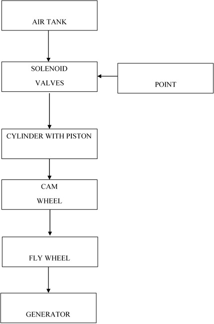
This project is developed for the users for generating Electricity using Air Engine. This project consists of a pneumatic cylinder & Piston, Direction Control Valve, Air foot pump, Air tank, Nylon hose plastic tube, tube fittings, Solenoid valves, Electronic point and Generator. The air foot pump is connected to the inlet of the air tank by means of plastic tube. The outlet of the valves are connected to the pneumatic cylinder through the nylon hose. There are two solenoid valves connected with the cylinder for the Engine operation. The solenoid valves are energized by the electronic point. The point controls the two valves alternatively to operate the piston of the cylinder according to the rotation of the fly wheel. The piston is connected with the cam wheel. When the first solenoid valve is energized, the air rushes to the cylinder and thus moves the piston up. This operates the cam wheel to rotate half cycle. Now the second solenoid valve is operated and thus exits the air from the cylinder. This operates the piston moves down and there by the cam wheel to rotate other half cycle and vice versa. Thus the wheel is continuously rotated. The generator is connected with the fly wheel.
BLOCK DIAGRAM
LINE DIAGRAM